eShop Search
Country and language
Choose country:
Choose language:
Apply

Thread-forming in metal

KOBSERT®

Installation tools for assembling thread inserts in metal materials

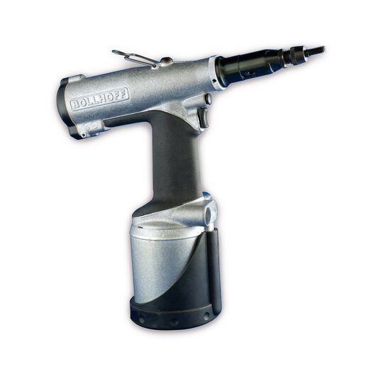
KOBSERT® 2005 K – Mechanical installation tool with hydraulic and pneumatic drive for cost-effective series assembly

Installation tools for manual assembly and series production

Highly durable, vibration-resistant and torsion-proof

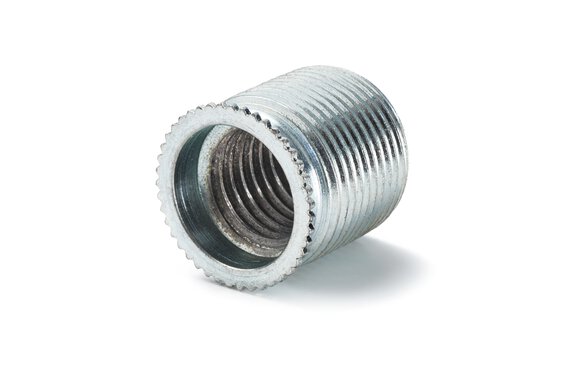
Our thread bushes are the ideal solution for creating highly durable, vibration-resistant and torsion-proof nut thread in metal materials with low shear strength, such as aluminium, aluminium alloys or magnesium alloys.

Method and principle

The installation procedure

Core hole

Twist drills with the dimensions specified in the thread standard should be used for the mounting thread.
Normally the core hole should not be countersunk. Deburring is permissible, but not larger than the nominal diameter of the mounting thread. If KOBSERT® is used with sealing ring or KOBSERT® HP, countersinking is always necessary.

Mounting thread

Metric ISO thread in accordance with DIN 13, cut with standard taps (6 H).
Standard DIN thread plug gauges should be used to verify that thread is true-to-gauge.

Installation

Manual or motor-driven installation tools are available to install the thread insert. The thread insert is screwed into the workpiece until the safety flange is resting on the surface of the workpiece. The installation procedure – pressing the safety flange into the workpiece – is carried out by a relative axial movement between the spindle, which has been screwed in, and the frontend assembly of the installation tool. The spindle is then removed again.

Removal

To remove KOBSERT® thread inserts from a workpiece, proceed as follows:

  1. Use a twist drill (Ø = external thread diameter) to drill into the safety flange as far as the thread.
  2. Lever out the safety flange using a triangular scraper or screwdriver.
  3. Insert a tool for unscrewing – or a suitable triangular scraper if necessary – into the internal thread to permit a transmission of forces. Turn the bush to the left to remove it.

Re-installation

Screw in a thread insert of the same nominal size until the safety flange is in the same position as before – turn it back slightly if necessary – and press it flat into the surface with the installation tool in the usual manner.
KOBSERT® Thread reinforcement in metals

Any questions?

We are here to assist you

Do you want to know more about our products or services? Our team will be happy to advise you.

Contact us

Find the right solution for your application

KOBSERT® installation tools

  • Type S4-S12

    Mode of operation

    Manual screw-in of thread insert and spindle, press in via thread spindle drive, and then manual spin-off. Indirect stroke limitation through manually applied torque.

    Technical data

    • Capacity up to 4 units/minute
    • Weight 0.5  to  1,0 kg
    • Max. setting stroke 12 mm
    • Max. setting force approx. 15 kN

    All types of KOBSERT® thread inserts can be installed (M 4 to M 12).

  • HH 830

    Mode of operation

    Manual screw-in of thread insert and spindle, hydraulic press in with lift lever and manual spin-off. Limited stroke due to stop ring. Change of wear parts by unscrewing the threaded mandrel and mouthpiece.

    Technical data

    • Capacity up to 3 units/min.
    • Weight 2.0 kg
    • Max. setting stroke 5.0 mm
    • Max. setting force 60 kN
    • For M 14 or larger, the spindle consists of two parts, spindle and adapter incl. HELICOIL® Plus Screwlock 

    All types of KOBSERT® thread inserts can be used (M 8 to M 30 x 1.5).

  • P 2005 K

    Mode of operation

    Spinning on the thread insert with touch automation on the mandrel. Hydraulic/pneumatic press-in as well as automatic spin-off through single button activation. Limited stroke due to adjusting ring. Change of threaded mandrel with bayonet lock.

    Technical Data

    • Capacity: up to 15 units/min.
    • Weight: 2.6 kg
    • Max. setting stroke: 7 mm
    • Max. setting force: 21 kN at 5.5 to 7 bar

    All types of KOBSERT® thread inserts can be used (M 4 to M 12 x 1.5).

  • PH 830

    Mode of operation

    Spinning on the thread insert through tilting lever actuation, hydraulic/pneumatic press-in procedure with separate activation or pedal actuation and spin-off? through tilting lever actuation. Limited stroke due to adjusting ring. Change of threaded mandrel with bayonet lock..

    Technical data

    • Capacity up to 10 units/min.
    • Weight 5.0 kg
    • Max. setting stroke 8.0 mm
    • Max. setting force 77 kN
    • From M 14 a stronger motor is used

    All types of KOBSERT® thread inserts can be used (M 8 to M 30 x 1.5).

Information and more

Downloads

Interested in KOBSERT®? Please download further information here.

We are happy to help

Do you have any questions or a current project?

Let us know – we will get in touch with you

Contact us